Introduction Into Design Engineering Week 12
Design considerations
In the preceding section learned to determine the stresses in rods,
bolts, and pins under simple loading conditions.
In engineering applications,
however, the determination of stresses is seldom an end in itself.
Rather, the knowledge of stresses is used by engineers
to assist in their most important task,
namely, the design of structures and machines
that will safely and economically perform a specified function.
Determination of the Ultimate Strength of a Material
An important element to be considered by a designer
is how the material that has been selected will behave under a load.
For a given material,
this is determined by performing specific tests
on prepared samples of the material.
For example,
a test specimen of steel may be prepared
and placed in laboratory testing machine
to be subjected to a known centric axial tensile force.
As the magnitude of the force is increased,
various changes in the specimen are measured,
for example, changes in its length and its diameter.
Eventually the largest force which may be applied
to the specimen is reached,
and the specimen either breaks or begins to carry less load.
This largest force is called the
ultimate load
for the test specimen and is denoted by $P_U$.
Since the applied load is centric,
it may be divided the
ultimate load by the
original cross-sectional area
of the rod to obtain the
ultimate normal stress of the material used.
This stress, also know as the ultimate strength
in tension of the material, is
$\sigma_U =\frac{P_U}{A} $
Several test procedures are available to determine
the ultimate shearing stress,
or ultimate strength in shear, of a material.
The one most commonly used involves the twisting of a circular tube.
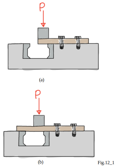 A most direct, if less accurate,
procedure consists in clamping a rectangular
or round bar in a shear tool (see in Fig.12_1(a))
and applying an increasing load $P$
until the ultimate load $P_U$ for single shear is obtained.
If the free end of the specimen rests
on both of the hardened dies (see in Fig.12_1(b)),
the ultimate load for double shear is obtained.
In either case,
the
ultimate shearing stress
$\tau_U$ is obtained
by dividing the ultimate load
by the total area over which shear has taken place.
It should be recalled that, in the case of single shear,
this area is the cross sectional area $A$ of the specimen,
while in double shear it is equal to twice the cross-sectional area.
A most direct, if less accurate,
procedure consists in clamping a rectangular
or round bar in a shear tool (see in Fig.12_1(a))
and applying an increasing load $P$
until the ultimate load $P_U$ for single shear is obtained.
If the free end of the specimen rests
on both of the hardened dies (see in Fig.12_1(b)),
the ultimate load for double shear is obtained.
In either case,
the
ultimate shearing stress
$\tau_U$ is obtained
by dividing the ultimate load
by the total area over which shear has taken place.
It should be recalled that, in the case of single shear,
this area is the cross sectional area $A$ of the specimen,
while in double shear it is equal to twice the cross-sectional area.
Allowable load and Allowable stress; Factor of Safety
The maximum load that a structural member
or a machine component will be allowed
to carry under normal conditions of utilization is considerably smaller
than the ultimate load.
This smaller load is referred to as
allowable load
and, sometimes, as the
working load or
design load .
Thus, only a fraction of the ultimate-load capacity of the member
is utilized when the allowable load is applied.
The remaining portion of the load-carrying capacity of the member
is kept in reserve to assure its safe performance.
The ratio of the ultimate load to the allowable load
is used to define the
factor of safety .
Factor of safety is
$Factor of safety = F.S. =\frac{ultimate load}{allowable load}$
...(eq.12_1)
An alternative definition of the factor of safety
is based on the use of stresses:
$Factor of safety = F.S. =\frac{ultimate stress}{allowable stres}$
...(eq.12_2)
Nevertheless, the
allowable-stress method
of design, based on the use of eq.12_2, is widely used.
In some fields of engineering,
notably aeronautical engineering,
the margin of safety is used in place of the factor of safety.
The margin of safety is defines
as the factor of safety minus one; that is,
$margin of safety = F.S. - 1.00 $
The two expressions given for the factor of safety
in eqs.(12_1) and (12_2) are identical
when a linear relationship exists between the load and the stress.
In most engineering applications,
however,this relationship ceases to be linear as the load approaches
its ultimate value,
and the factor of safety obtained from eq.(12_2) does not provide
a true assessment of the safety of a given design.