Introduction Into Design Engineering Week 11
Stress under general loading conditions; components of stress
 The examples of the previous sections were limited
to members under axial loading and connections under transverse loading.
Most structural members and machine components are
under more involved loading conditions.
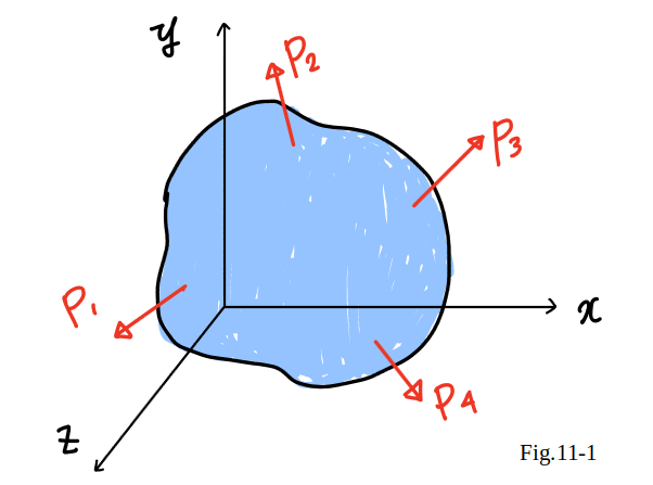
Consider a body subjected to several loads
P1, P2, etc. (Fig.11_1).
To understand the stress condition
created by these loads at some point
Q
within the body,
it shall be first passed a section through
Q ,
using a plane parallel to the
yz
plane.
The portion of the body to the left of the section is subjected
to some of the original loads,
and to normal and shearing forces distributed over the section.
The examples of the previous sections were limited
to members under axial loading and connections under transverse loading.
Most structural members and machine components are
under more involved loading conditions.
Consider a body subjected to several loads
P1, P2, etc. (Fig.11_1).
To understand the stress condition
created by these loads at some point
Q
within the body,
it shall be first passed a section through
Q ,
using a plane parallel to the
yz
plane.
The portion of the body to the left of the section is subjected
to some of the original loads,
and to normal and shearing forces distributed over the section.
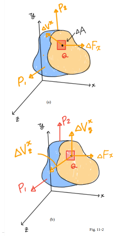 It shall be denoted by
$\Delta F^x$ and $\Delta V^x$,
respectively,
the normal and the shearing forces
acting on a small area $\Delta A$
surrounding point
Q (Fig.11_2(a)).
Note that the superscript $x$
is used to indicate that the force
$\Delta F^x$ and $\Delta V^x$ act on a surface perpendicular
to the $x$ axis.
While the normal force $\Delta F^x$ has a well-defined direction,
the shearing force $\Delta V^x$ may have any direction
in the plane of the section.
Therefore, it should be resolved $\Delta V^x$ into two component forces,
$\Delta$ $V^{x}_{y}$
and
$\Delta$ $V^{x}_{z}$
in directions parallel to the $y$ and $z$ axes, respectively (Fig.11_2 (b)).
It shall be denoted by
$\Delta F^x$ and $\Delta V^x$,
respectively,
the normal and the shearing forces
acting on a small area $\Delta A$
surrounding point
Q (Fig.11_2(a)).
Note that the superscript $x$
is used to indicate that the force
$\Delta F^x$ and $\Delta V^x$ act on a surface perpendicular
to the $x$ axis.
While the normal force $\Delta F^x$ has a well-defined direction,
the shearing force $\Delta V^x$ may have any direction
in the plane of the section.
Therefore, it should be resolved $\Delta V^x$ into two component forces,
$\Delta$ $V^{x}_{y}$
and
$\Delta$ $V^{x}_{z}$
in directions parallel to the $y$ and $z$ axes, respectively (Fig.11_2 (b)).
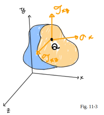 Dividing now the magnitude of each force by the area
$\Delta A$,
and letting $\Delta A$ approach zero,
it is defined the three stress components shown in Fig.11_3:
$
{\displaystyle
\sigma_{x}=\lim_{\Delta A \to 0}\frac{\Delta F^x}{\Delta A}
}
$
$
{\displaystyle
\tau_{xy}=\lim_{\Delta A \to 0}\frac{\Delta V^x_y}{\Delta A}
}
$
$
{\displaystyle
\tau_{xz}=\lim_{\Delta A \to 0}\frac{\Delta V^x_z}{\Delta A}
}
$
It is noted that the first subscript in
$\sigma_x$, $\tau_{xy}$, and $\tau_{xz}$
is used to indicate that the stresses under consideration
are exerted on a surface perpendicular to the $x$ axis.
The second subscript in
$\tau_{xy}$, and $\tau_{xz}$
identifies
the direction of the component.
The normal stress $\sigma_x$ is positive
if the corresponding arrow points in the positive $x$ direction,
i.e., if the body is in tension, and negative otherwise.
Similarly, the shearing stress components
$\tau_{xy}$, and $\tau_{xz}$ are positive
if the corresponding arrows point,
respectively, in the positive $y$ and $z$ directions.
Dividing now the magnitude of each force by the area
$\Delta A$,
and letting $\Delta A$ approach zero,
it is defined the three stress components shown in Fig.11_3:
$
{\displaystyle
\sigma_{x}=\lim_{\Delta A \to 0}\frac{\Delta F^x}{\Delta A}
}
$
$
{\displaystyle
\tau_{xy}=\lim_{\Delta A \to 0}\frac{\Delta V^x_y}{\Delta A}
}
$
$
{\displaystyle
\tau_{xz}=\lim_{\Delta A \to 0}\frac{\Delta V^x_z}{\Delta A}
}
$
It is noted that the first subscript in
$\sigma_x$, $\tau_{xy}$, and $\tau_{xz}$
is used to indicate that the stresses under consideration
are exerted on a surface perpendicular to the $x$ axis.
The second subscript in
$\tau_{xy}$, and $\tau_{xz}$
identifies
the direction of the component.
The normal stress $\sigma_x$ is positive
if the corresponding arrow points in the positive $x$ direction,
i.e., if the body is in tension, and negative otherwise.
Similarly, the shearing stress components
$\tau_{xy}$, and $\tau_{xz}$ are positive
if the corresponding arrows point,
respectively, in the positive $y$ and $z$ directions.
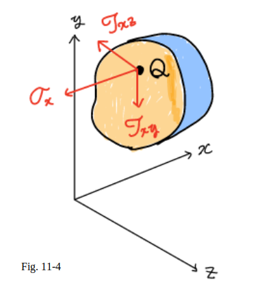 The above analysis may also be carried out
by considering the portion of body located to the right
of the vertical plane through $Q$ (Fig.11_4).
The same magnitudes,
but opposite directions,
are obtained for the normal and shearing forces
$\Delta F_x$,$\Delta V^x_y$ and $\Delta V^x_z$.
Therefore, the same values are also obtained
for the corresponding stress components,
but since the section in Fig.11_4 now faces the negative $x$ axis,
a positive sign for $\sigma_x$ will indicate
that the corresponding arrow points in the negative $x$ direction.
Similarly, positive signs for
$\tau_{xy}$ and $\tau_{xz}$ will indicate
that the corresponding arrows point, respectively,
in the negative $y$ and $z$ directions, as shown in Fig.11_4.
Passing a section through $Q$ parallel to the $zx$ plane,
it is defined in the same manner the stress components,
$\sigma_y$,$\tau_{yz}$, and $\tau_{yz}$.
Finally, a section through $Q$ parallel to the $xy$ plane yields
the components $\sigma_z$, $\tau_{zx}$, and $\tau_{zy}$.
The above analysis may also be carried out
by considering the portion of body located to the right
of the vertical plane through $Q$ (Fig.11_4).
The same magnitudes,
but opposite directions,
are obtained for the normal and shearing forces
$\Delta F_x$,$\Delta V^x_y$ and $\Delta V^x_z$.
Therefore, the same values are also obtained
for the corresponding stress components,
but since the section in Fig.11_4 now faces the negative $x$ axis,
a positive sign for $\sigma_x$ will indicate
that the corresponding arrow points in the negative $x$ direction.
Similarly, positive signs for
$\tau_{xy}$ and $\tau_{xz}$ will indicate
that the corresponding arrows point, respectively,
in the negative $y$ and $z$ directions, as shown in Fig.11_4.
Passing a section through $Q$ parallel to the $zx$ plane,
it is defined in the same manner the stress components,
$\sigma_y$,$\tau_{yz}$, and $\tau_{yz}$.
Finally, a section through $Q$ parallel to the $xy$ plane yields
the components $\sigma_z$, $\tau_{zx}$, and $\tau_{zy}$.
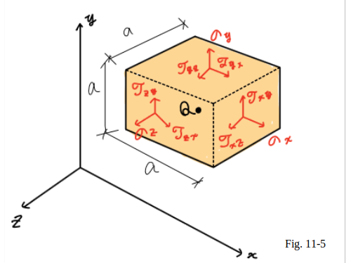 To facilitate the visualization of the stress condition at point $Q$,
it shall be considered a small cube of side a centered at $Q$
and the stresses exerted on each of the six faces of the cube (Fig.11_5).
The stress components shown in the figure are
$\sigma_x$,$\sigma_y$, and $\sigma_z$,
which represent
the normal stress
on faces respectively perpendicular to the
$x$, $y$, and $z$ axes,
and the six
shearing stress components
$\tau_{xy}$, $\tau_{xz}$, etc .
According to the definition of the shearing stress components,
$\tau_{xy}$ represents the $y$ component of the shearing stress
exerted on the face perpendicular to the $x$ axis,
while $\tau_{yx}$ represents the $x$ component of the shearing stress
exerted on the face perpendicular to the $y$ axis.
Note that only three faces of the cube are actually visible
in Fig.11_5,
and that equal and opposite
stress components act on the hidden faces.
While the stresses acting on the faces of the cube
differ slightly from the stresses at $Q$,
the error
involved is small and vanishes as side a of the cube approaches
zero .
To facilitate the visualization of the stress condition at point $Q$,
it shall be considered a small cube of side a centered at $Q$
and the stresses exerted on each of the six faces of the cube (Fig.11_5).
The stress components shown in the figure are
$\sigma_x$,$\sigma_y$, and $\sigma_z$,
which represent
the normal stress
on faces respectively perpendicular to the
$x$, $y$, and $z$ axes,
and the six
shearing stress components
$\tau_{xy}$, $\tau_{xz}$, etc .
According to the definition of the shearing stress components,
$\tau_{xy}$ represents the $y$ component of the shearing stress
exerted on the face perpendicular to the $x$ axis,
while $\tau_{yx}$ represents the $x$ component of the shearing stress
exerted on the face perpendicular to the $y$ axis.
Note that only three faces of the cube are actually visible
in Fig.11_5,
and that equal and opposite
stress components act on the hidden faces.
While the stresses acting on the faces of the cube
differ slightly from the stresses at $Q$,
the error
involved is small and vanishes as side a of the cube approaches
zero .
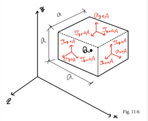 Important relations among the shearing stress components will now be derived.
Let’s consider the free-body diagram
of the small cube centered at point $Q$ (Fig.11_6).
The normal and shearing forces acting on the various faces
of the cube are obtained by multiplying
the corresponding stress components by the area $\Delta A$ of each face.
At first, these three equilibrium equations can be written;
$\Sigma F_x = 0$,
$\Sigma F_y = 0$,
$\Sigma F_z = 0$ ... (eq.11_1)
Since forces equal and opposite to the forces actually
shown in Fig.11_6 are acting on the hidden faces of the cube,
it is clear that Eq.11_1 are satisfied.
Considering now the moments of the forces about axes
$Q’_x$, $Q’_y$, and $Q’_z$ drawn from $Q$
in directions respectively parallel to the $x$, $y$, and $z$ axes,
three additional equations are written:
$\Sigma M_{x'} = 0$,
$\Sigma M_{y'} = 0$,
$\Sigma M_{z'} = 0$ ... (eq.11_1)
Important relations among the shearing stress components will now be derived.
Let’s consider the free-body diagram
of the small cube centered at point $Q$ (Fig.11_6).
The normal and shearing forces acting on the various faces
of the cube are obtained by multiplying
the corresponding stress components by the area $\Delta A$ of each face.
At first, these three equilibrium equations can be written;
$\Sigma F_x = 0$,
$\Sigma F_y = 0$,
$\Sigma F_z = 0$ ... (eq.11_1)
Since forces equal and opposite to the forces actually
shown in Fig.11_6 are acting on the hidden faces of the cube,
it is clear that Eq.11_1 are satisfied.
Considering now the moments of the forces about axes
$Q’_x$, $Q’_y$, and $Q’_z$ drawn from $Q$
in directions respectively parallel to the $x$, $y$, and $z$ axes,
three additional equations are written:
$\Sigma M_{x'} = 0$,
$\Sigma M_{y'} = 0$,
$\Sigma M_{z'} = 0$ ... (eq.11_1)
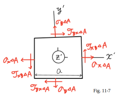 Using a projection on the $x’$ $y’$ plane (Fig.11_7),
it is noted that the only forces with moments about the $z$ axis
different from $zero$ are the shearing forces.
These forces form two couples,
one of counterclockwise (positive) moment
($\tau_{xy} \Delta A$)$a$,
the other of clockwise (negative) moment
$-$($\tau_{xy} \Delta A$)$a$.
The last of the three Eq 11_1 yields, therefore,
$+⤴ $$\Sigma M_Z = 0$ :
($\tau_{xy} \Delta A$)$a$ $-$($\tau_{xy} \Delta A$)$a$$=0$
Using a projection on the $x’$ $y’$ plane (Fig.11_7),
it is noted that the only forces with moments about the $z$ axis
different from $zero$ are the shearing forces.
These forces form two couples,
one of counterclockwise (positive) moment
($\tau_{xy} \Delta A$)$a$,
the other of clockwise (negative) moment
$-$($\tau_{xy} \Delta A$)$a$.
The last of the three Eq 11_1 yields, therefore,
$+⤴ $$\Sigma M_Z = 0$ :
($\tau_{xy} \Delta A$)$a$ $-$($\tau_{xy} \Delta A$)$a$$=0$
From which it is concluded that
$\tau_{yx} = \tau_{yx}$ ...(eq.11_2)
The relation obtained shows that the $y$ component
of the shearing stress exerted
on a face perpendicular to the $x$ axis
is equal to the $x$ component
of the shearing stress exerted on a face perpendicular to the $y$ axis.
From the remaining two equations 11_1,
it is derived in a similar manner the relations
$\tau_{yz} = \tau_{zy}$, $\tau_{zx} = \tau_{xz}$ ...(eq.11_3)
It is concluded from eq.11_2 and eq.11_3
that only six stress components are required
to define the condition of stress at a given point $Q$,
instead of nine as originally assumed.
These six components are
$\sigma_x$, $\sigma_y$, $\sigma_z$,
$\tau_{xy}$,$\tau_{yz}$, and $\tau_{zx}$.
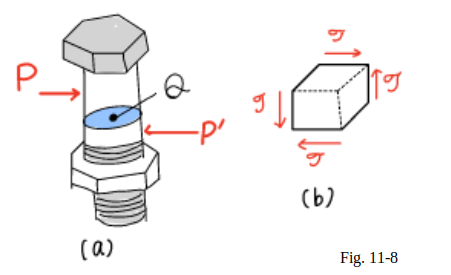 It is noted that,
at a given point,
shear cannot take place in one plane only;
an equal shearing stress must be exerted
on another plane perpendicular to the first one.
For example,
considering the bolt and a small cube at the center $Q$
of the bolt (Fig.11_8(a)),
it is found that shearing stresses of equal magnitude
must be exerted on the two horizontal faces
of the cube and on the two face
that are perpendicular to the forces $P$ and $P’$ (Fig.11_8(b)).
Before concluding our discussion of stress components,
let’s consider again the case of a member under axial loading.
It is noted that,
at a given point,
shear cannot take place in one plane only;
an equal shearing stress must be exerted
on another plane perpendicular to the first one.
For example,
considering the bolt and a small cube at the center $Q$
of the bolt (Fig.11_8(a)),
it is found that shearing stresses of equal magnitude
must be exerted on the two horizontal faces
of the cube and on the two face
that are perpendicular to the forces $P$ and $P’$ (Fig.11_8(b)).
Before concluding our discussion of stress components,
let’s consider again the case of a member under axial loading.
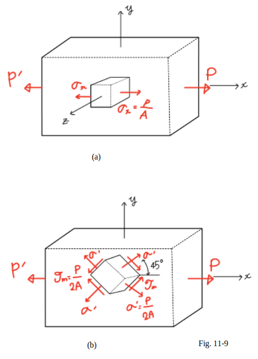
 If it is considered a small cube with faces respectively
parallel to the faces of the member
and recall the results obtained in week 10,
it is found that the conditions of stresses are
normal stresses $\sigma_x$ exerted
on the faces of the cube which are perpendicular to the $x$ axis.
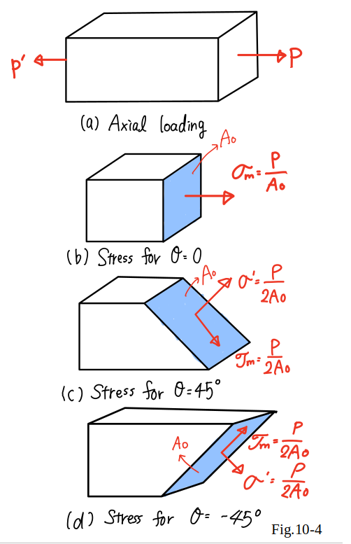
However, if the small cube is rotated by $45°$
about the $z$ axis
so that its new orientation matches the orientation of the sections
considered in Fig.10_4(c) and (d),
it is concluded that normal and shearing stresses
of equal magnitude are exerted on four faces of the cube (Fig. 11_9(b)).
Thus, it should be observed that the same loading condition
may lead to different interpretations of the stress situation
at a given point,
depending upon the orientation of the element considered.
If it is considered a small cube with faces respectively
parallel to the faces of the member
and recall the results obtained in week 10,
it is found that the conditions of stresses are
normal stresses $\sigma_x$ exerted
on the faces of the cube which are perpendicular to the $x$ axis.
However, if the small cube is rotated by $45°$
about the $z$ axis
so that its new orientation matches the orientation of the sections
considered in Fig.10_4(c) and (d),
it is concluded that normal and shearing stresses
of equal magnitude are exerted on four faces of the cube (Fig. 11_9(b)).
Thus, it should be observed that the same loading condition
may lead to different interpretations of the stress situation
at a given point,
depending upon the orientation of the element considered.
Please go to the webclass and answer the question.