Processing math: 51%
Introduction Into Design Engineering Week 10
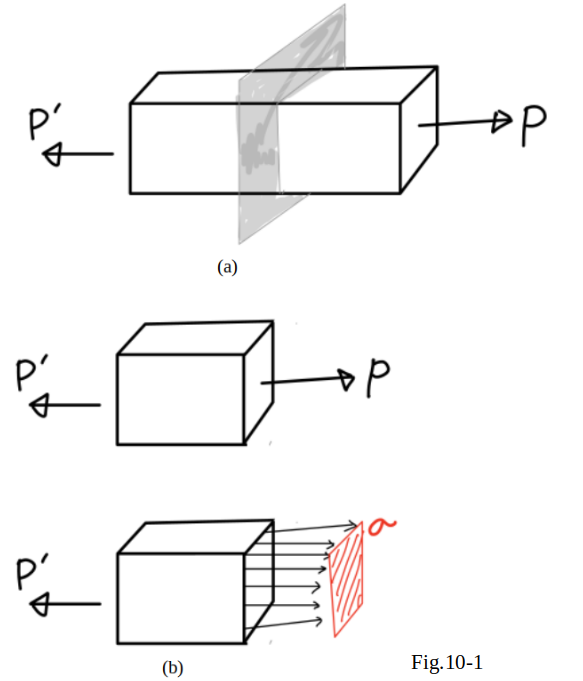 In the previous sessions, axial force exerted on a
two-force member
(see in Fig.10_1(a)) were found to cause
normal stress
in that member (see in Fig.10_1(b)).
In the previous sessions, axial force exerted on a
two-force member
(see in Fig.10_1(a)) were found to cause
normal stress
in that member (see in Fig.10_1(b)).
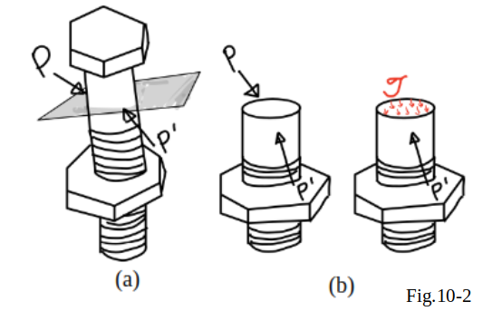
While
transverse forces
exerted on bolts and pins (Fig.10_2(a)) were found to cause
shearing stresses
in those connections(Fig.10_2(b)).
The reason such a relation was observed between
axial forces
and
normal stresses
on one hand,
and
transverse forces
and
shearing stresses
on the other, was because stresses
were being determined only on planes
perpendicular to the axis of the member or connection.
As it will be seen in this section,
axial forces
cause both
normal and shearing stresses
on planes which are not perpendicular to the axis of the member.
Similarly,
transverse forces
exerted on a
bolt or a pin
cause both
normal and shearing stresses
on planes which are
not perpendicular
to the axis of the bolt or pin.
 Consider the two-force member of Fig.10_1,
which is subjected to axial forces
P
and
P’.
Consider the two-force member of Fig.10_1,
which is subjected to axial forces
P
and
P’.
If we pass a section forming an angle θ
with a normal plane (Fig.10_3(a))
and draw the free-body diagram of the portion of member
located to the left that section (Fig.10_3(b)),
it would be found from the equilibrium conditions of the free body
that the distributed forces acting on the section
must be equivalent to the force
P .
Resolving
P
into components
F
and
V ,
respectively normal and tangential to the section (Fig.10_3(c)),
it should be;
F=Pcosθ ....(eq.10_1)
V=Psinθ ....(eq.10_2)
The force
F
represents the resultant of normal forces distributed over the section,
and the force
V
the resultant of shearing forces (Fig.10_3 (c) and (d)).
The average values of the corresponding
normal and shearing stresses are obtained by dividing, respectively,
F
and
V
by the area Aθ of the section;
σ=FAθ ...(eq.10_3)
τ=VAθ ...(eq.10_4)
Substituting for
F
and
V from (eq.10_1) and (eq.10_2)
into (wq.10_3) and (eq.10_4) respectively,
and observing from Fig.10_3(c) that
A0=Aθcosθ
or
Aθ=A0cosθ
where A0
denoted the area of a section perpendicular to the axis of the member.
These equations will be obtained
σ=PcosθA0/cosθ
τ=PsinθA0/cosθ
or
σ=PA0cos2θ ...(eq.10_5)
τ=PA0sinθcosθ ...(eq.10_6)
 It should be noted from eq.10_5 that the normal stress
σ is maximum when
θ=0,
i.e., when the plane of the section is
perpendicular to the axis of the member,
and that it approaches
zero
as
σ approaches
\theta =90°.
It should be noted from eq.10_5 that the normal stress
σ is maximum when
θ=0,
i.e., when the plane of the section is
perpendicular to the axis of the member,
and that it approaches
zero
as
σ approaches
\theta =90°.
The value of \sigma
should be checked when
\sigma =0, it should be
\sigma_{m}=\frac{P}{A_0} ...(eq.10_7)
as it is found earlier session.
The second of eq.10_6 shows that
the shearing stress \tau is zero for
\sigma =0 and \sigma =90°,
and that for
\sigma =45° it reaches its maximum value,
\tau_{m}=\frac{P}{A_0}\sin45°\cos45°=\frac{P}{2A_0} ...(eq.10_8)
The equation 10_7 indicates that,
when \sigma =45°,
the normal stress \sigma’ is also equal to
\frac{P}{2A_0}:
\sigma’=\frac{p}{A_0}\cos^2{45°}=\frac{P}{2A_0} ...(eq.10_9)
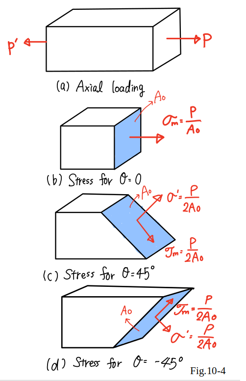
The results obtained in Eqs.(10_7), (10_8), and (10_9)
are shown graphically in Fig.10_4.
It is noted that when the same loading
may produce either a normal stress
\sigma_{m}=\frac{P}{A_0}
and no shearing stress (Fig.10_4(b)),
or a normal and shearing stress of the same magnitude
\sigma’=\tau=\frac{p}{A_0}
(Fig.10_4 (c) and (d)),
depending upon the orientation of the section.
Please go to the webclass and answer the question(s) shown in webclass.