はじめに†
- Salome-Mecaで行う(FEM解析全般に言えることだけど)計算は、「弾性解析」と「弾塑性解析」があります。
- 弾性解析→物体にかかる力がゼロになったときに、もとの形に戻る
- 弾塑性解析→物体にかかる力がゼロになったときに、もとの形に戻らない(変形したまま)
- また、弾性解析は荷重-変位のグラフが直線になるのに対し、弾塑性解析はグラフが直線になりません。このことから弾塑性解析の方法を「材料非線形」とも言います。
- (ここの説明、誰か詳しい方補足お願いしたいです・・・)
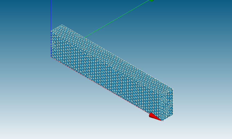
- モデルについて、今回はシンプルな片持ち梁、先端荷重で行います。
- 使用ツールについて、今回の説明ではSalome-Meca2019を使用しています。
Salome-Mecaの起動→ジオメトリの作成†
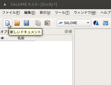
Salome-Meca2019を起動†
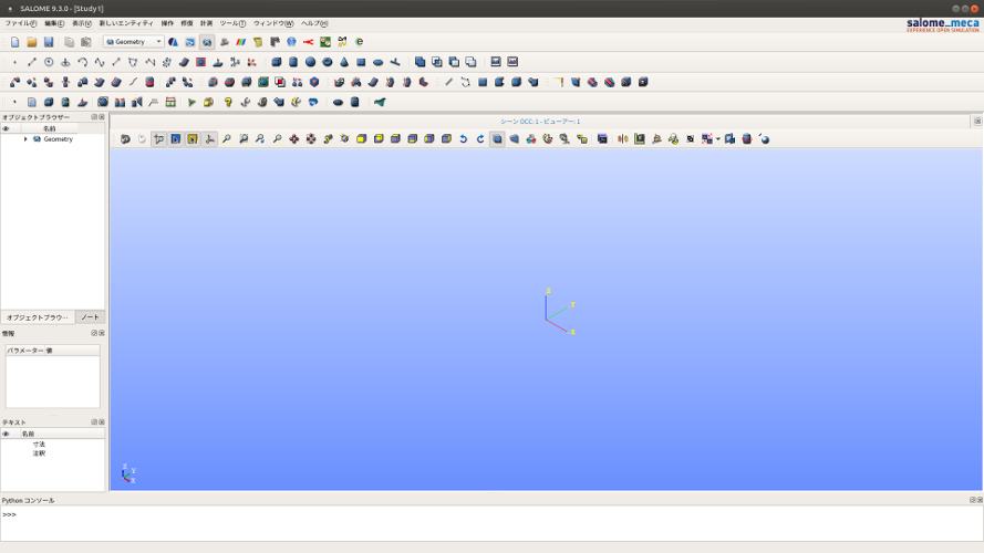
プルダウンメニューから「Geometry」を選択†
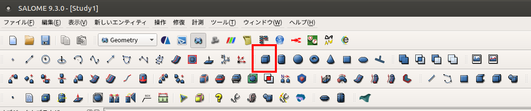
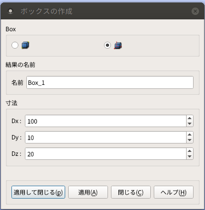
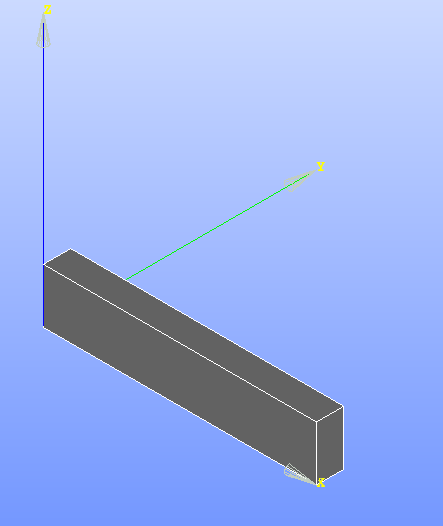
ボックスの作成†
- Dx=100,Dy=10,Dz=20→適用して閉じる
ジオメトリのグループの作成†
- 後で載荷面、固定面の設定をするために必要な箇所について、この段階でグループを作成します。
- オブジェクトブラウザーの「Box_1」のところで右クリック→「グループを作成」をクリック
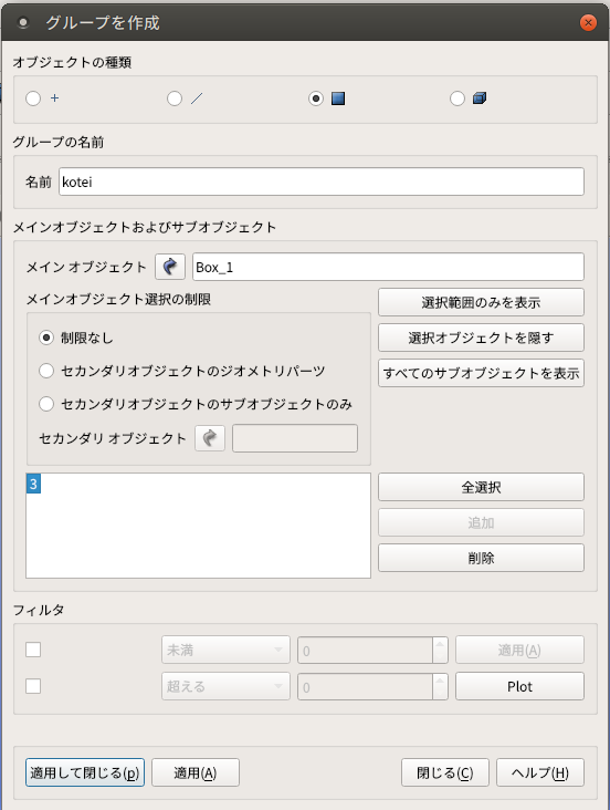
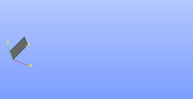
固定面†
- 「オブジェクトの種類」のところで右から2番目の□にチェックを入れる
- 原点側の面をクリック→追加
- 名前をわかりやすいようにつける(ここでは「kotei」とする)→適用して閉じる
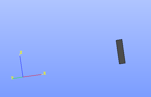
載荷面†
- 「オブジェクトの種類」のところで右から2番目の□にチェックを入れる
- 載荷面の反対の面をクリック→追加
- 名前をわかりやすいようにつける(ここでは「saika」とする)→適用して閉じる
メッシュの作成†
メッシュの切り方の設定†
- プルダウンメニューから「Mesh」を選択
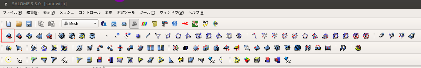
- オブジェクトブラウザーで、上で作成した「Box_1」を選択→メッシュを作成(左側にある方)を選択
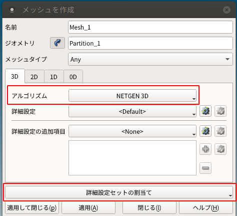
- 3D→アルゴリズム「NETGEN 3D」を選択→詳細設定セットの割当て→「3D Automatic Tetrahedralization」をクリック
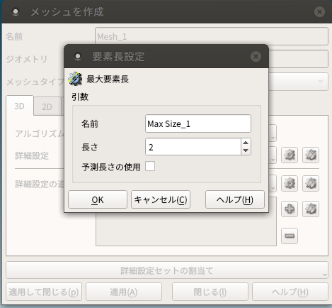
- 要素長設定(メッシュの細かさの設定)をする。モデルに対してあまりにも大きいと思ったような解析結果にならず、逆に細かいと計算に時間がかかったりエラーが出たりする。
- 今回はDx=100,Dy=10,Dz=20のモデルのため、最大要素長=2とする。長さのところに「2」を入力→ok
メッシュを切る†
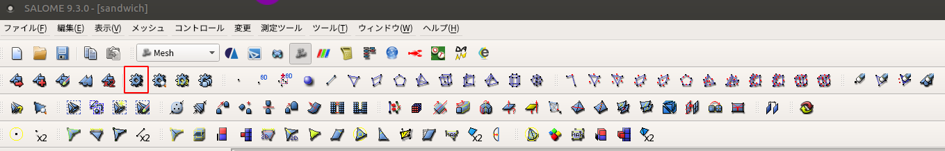
- オブジェクトブラウザーで、上で作成した「Mesh_1」を選択→メッシュを作成(右側にある方)を選択
グループの作成†
- ジオメトリで作成したグループをメッシュに反映させる
- 「Mesh_1」で右クリック→「ジオメトリのグループを作成」をクリック
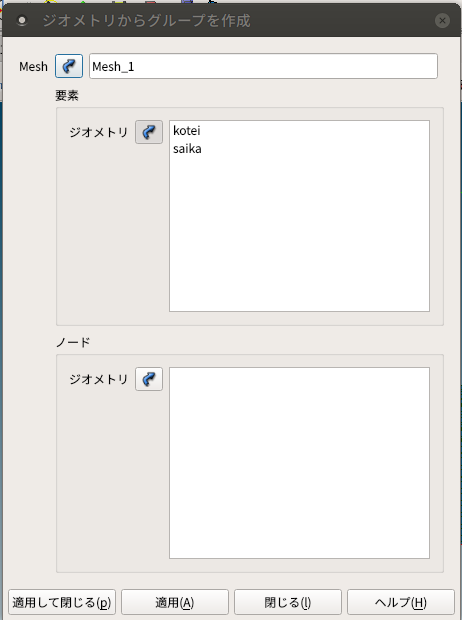
- Geometryで作成したBox_1のグループ「saika」「kotei」を選択→適用して閉じる
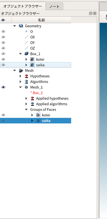
- オブジェクトブラウザーに反映され画像のようになっていれば成功
- メッシュの作成は以上
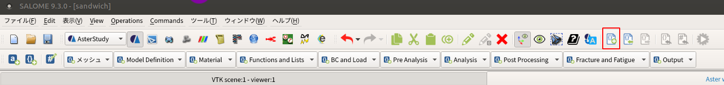
AsterStudyの設定†
メッシュ†
- メッシュファイルを読み込む設定をします
- 「メッシュ」→「Read a Mesh」を選択

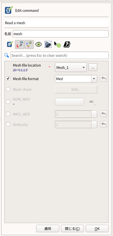
- Mesh file location:Mesh_1(作成したメッシュ)、Mesh file format:Med を選択してok
- 左下のInfomationにこのように表示されればok
 mesh = LIRE_MAILLAGE(
 FORMAT='MED',
 UNITE=20
Model Definition†
- 解析の方法の設定をします
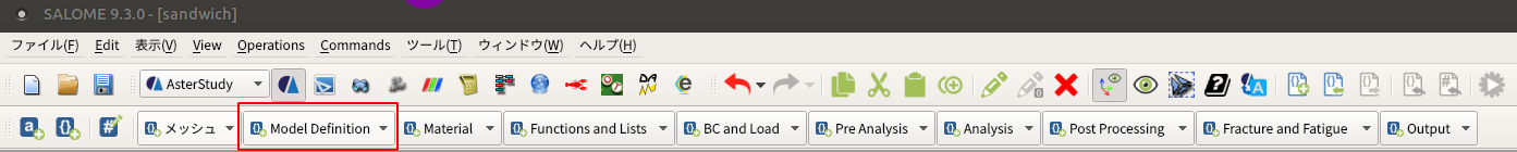
- 「Model Definition」→「Assign finite element」を選択
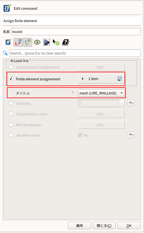
- 「メッシュ」が「mesh(LIRE_MAILLAGE)」になっているか確認
- 「Finite element assignement」を1itemに増やす→「Edit」
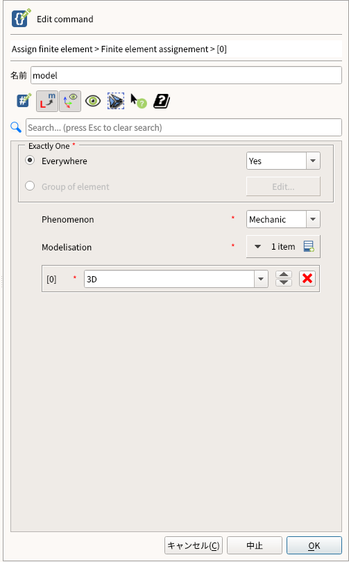
- Everywhere:Yes Phenomenon:Mechanic Modelisation:3Dを選択→ok
- 左下のInfomationにこのように表示されればok
model = AFFE_MODELE(
 AFFE=_F(
   MODELISATION=('3D', ),
   PHENOMENE='MECANIQUE',
   TOUT='OUI'
 ),
 MAILLAGE=mesh
)
Material†
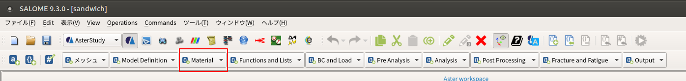
- 上のメニューの「Material」から「Define a material」を選択
![[PukiWiki]](image/pukiwiki.png "[PukiWiki]")